SHARE
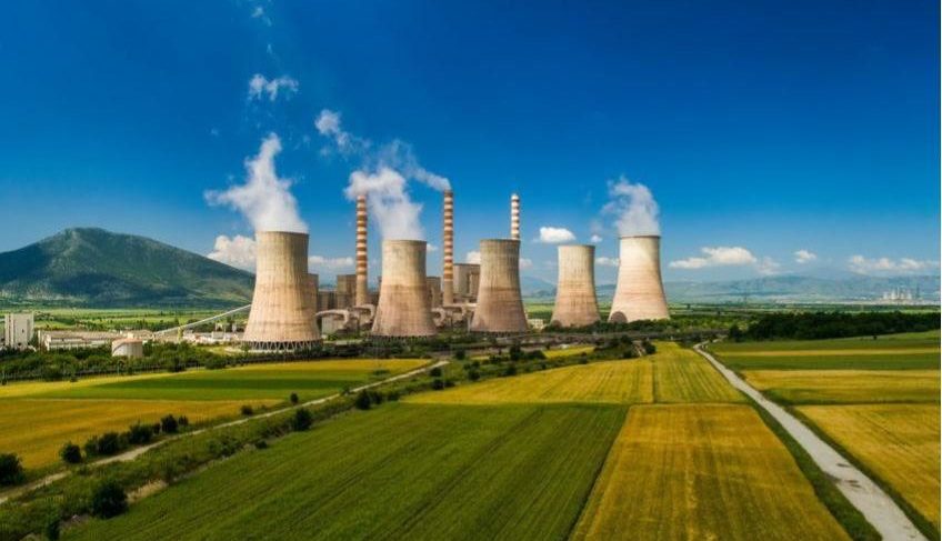
Waste to Energy (WTE) and Thermal Renewable sector in the EU
Alessandro Lagazio, one of the finalists of the Road Delineator Maintenance Challenge, by Ferrovial and Cintra, shares with us his views on Waste to Energy (WTE) and the Thermal Renewable sector in the EU. Alessandro is the business owner of the Geneva-based LA Consulting, a consulting company specialized in Mechanical Engineering. He wrote this article in collaboration with Roberto Palazzolo.
Nowadays, green energy is definitely hyped. Generally, as soon as somebody thinks about renewables, the first thing that comes to mind is to use wind or solar (photovoltaic) power as a source. Being an engineer and working with complex and different systems drives my curiosity to better understand the status of green energy in Europe. It also helps me to make an objective assessment of the situation without "trendy" biases. The Eurostat website is definitely the starting point for such an assessment.
At first glance, good news pops up. The gross available energy in EU from renewables and biofuels has increased steadily over the past years, as shown in the below figures:
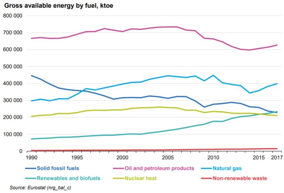 Several causes are behind this increase in the sector. For sure, one of the drivers is that institutions have issued ambitious goals to reduce CO2 emissions in the past years. However, they have also initiated a system for monitoring and sharing the best available techniques (BAT) to achieve lower polluting emissions in general, thus enabling wider use of biofuels and waste without increasing their environmental impact.
Among renewable energy sources or green energy sources, the waste-to-energy sector has flourished and it deserves to be further investigated due to its technological challenges.
Waste is actually not a "green" energy source per se, or at least not completely: only part of the municipal solid waste (biomass) can be classified as CO2-neutral. However, waste is continuously produced every year by everyone (municipal solid waste) and it should go through some kind of treatment if it cannot be reused or recycled.
Let's focus on MSW (municipal solid waste) which has the advantage to have proven and mature systems for the recycle and the energy recovery (WTE plants). From Eurostat, it is possible to see the MSW yearly production.
Several causes are behind this increase in the sector. For sure, one of the drivers is that institutions have issued ambitious goals to reduce CO2 emissions in the past years. However, they have also initiated a system for monitoring and sharing the best available techniques (BAT) to achieve lower polluting emissions in general, thus enabling wider use of biofuels and waste without increasing their environmental impact.
Among renewable energy sources or green energy sources, the waste-to-energy sector has flourished and it deserves to be further investigated due to its technological challenges.
Waste is actually not a "green" energy source per se, or at least not completely: only part of the municipal solid waste (biomass) can be classified as CO2-neutral. However, waste is continuously produced every year by everyone (municipal solid waste) and it should go through some kind of treatment if it cannot be reused or recycled.
Let's focus on MSW (municipal solid waste) which has the advantage to have proven and mature systems for the recycle and the energy recovery (WTE plants). From Eurostat, it is possible to see the MSW yearly production.
 Municipal waste treatment, EU-28, 1995-2018 (kg per capita)
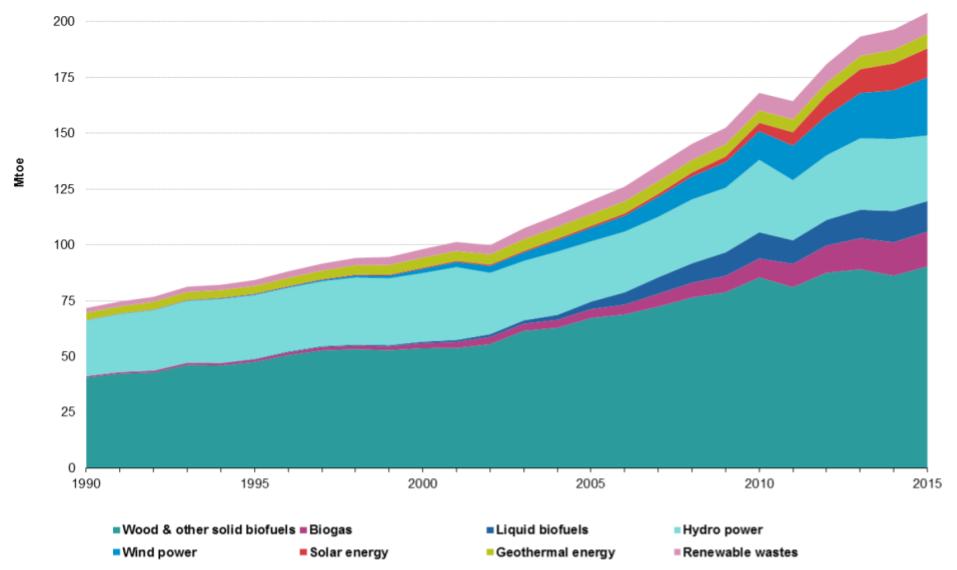 Primary production of energy from renewable sources, EU-28, 1990-2015Source: Eurostat (nrg110a)
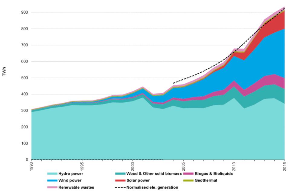 Gross electricity generation from renewable sources, EU-28, 1990-2015Source: Eurostat (nrg105a)
Among the several publications issued by Eurostat, a very interesting one drives attention to the use of renewable for heating and cooling.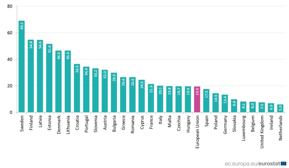 Share of the total energy used for heating and cooling coming from renewable sources, 2017 (%)
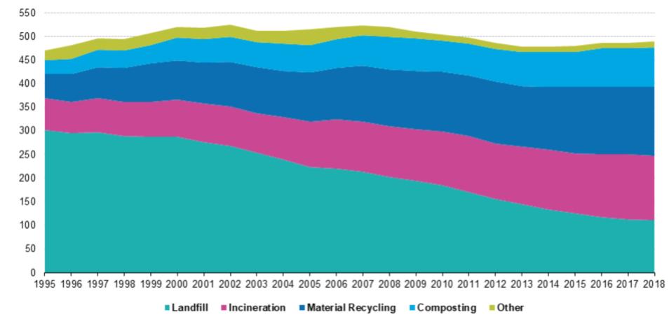
In EU the share of total renewable energy used for district heating is already around 20% on average, with a peak in Sweden of nearly 70%. This is in compliance with the trends related to waste incineration with energy recovery of municipal solid waste, which has doubled its capacity in the last 20 years. In the Table below the data on the different MSW treatment methods are given.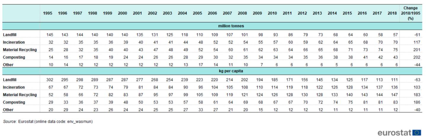 Municipal waste landfilled, incinerated, recycled and composted, EU-28, 1995-2018
After assessing the importance of Waste to Energy (WTE) as a method to recover energy from MSW, it is mandatory to introduce here a brief description of a modern state-of-the-art WTE plant. The EU's best available techniques for each industrial sector are aimed at the minimization of the pollution, have been issued by JRC (EU joint research center), and are available on their website. Among other sectors, also for Waste Incineration, a compendium of the best available techniques has been issued by JRC where a simple sketch showing the relevant sections of a modern Waste to Energy (WTE) plant is presented (data from https://eippcb.jrc.ec.europa.eu/sites/default/files/2020-01/JRC118637_WI_Bref_2019_published_0.pdf). See the different sections in the figure below: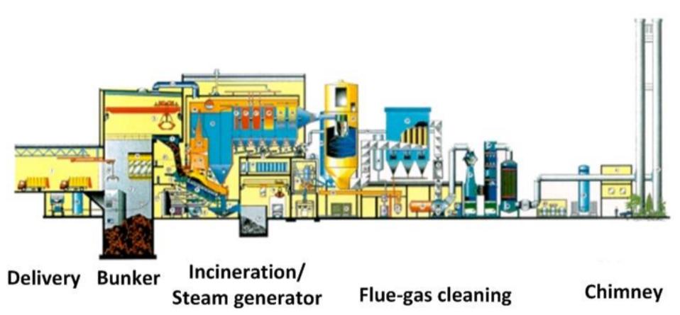 Sections of an MSW WTE Plant with a wet flue gas cleaning system
A typical waste incineration plant will include the following sections: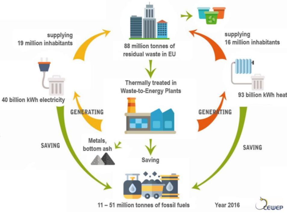 Traditionally, the focus on Waste to Energy (WTE) has always been on the FGC since it needs several stages to ensure that air pollution is limited as much as possible.
There are two main types of DeNOX technologies:
Traditionally, the focus on Waste to Energy (WTE) has always been on the FGC since it needs several stages to ensure that air pollution is limited as much as possible.
There are two main types of DeNOX technologies:
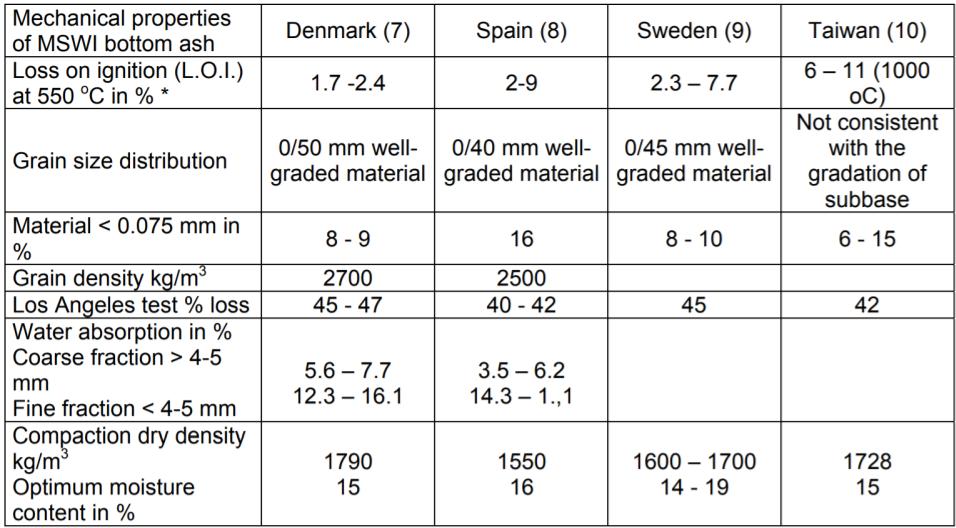 * Modern WTE-plants are capable of achieving low LOI’s (<2 percent)
Testing results for mechanical properties of Municipal Solid Waste Incineration Bottom Ash (MSWIBA) from selected countries. The grain size distribution is classified as well-graded, meaning that there is an equal abundance of coarse and fine material. Such uniform gradation is important to the compatibility of bottom ash and the potential to utilize bottom ash as an aggregate substitute.
If you want to participate in challenges that deal with this kind of issues (e.g. waste management, recycling, renewable energies, etc.), discover what ennomotive can do for you.
Join the engineering community
* Modern WTE-plants are capable of achieving low LOI’s (<2 percent)
Testing results for mechanical properties of Municipal Solid Waste Incineration Bottom Ash (MSWIBA) from selected countries. The grain size distribution is classified as well-graded, meaning that there is an equal abundance of coarse and fine material. Such uniform gradation is important to the compatibility of bottom ash and the potential to utilize bottom ash as an aggregate substitute.
If you want to participate in challenges that deal with this kind of issues (e.g. waste management, recycling, renewable energies, etc.), discover what ennomotive can do for you.
Join the engineering community
Several causes are behind this increase in the sector. For sure, one of the drivers is that institutions have issued ambitious goals to reduce CO2 emissions in the past years. However, they have also initiated a system for monitoring and sharing the best available techniques (BAT) to achieve lower polluting emissions in general, thus enabling wider use of biofuels and waste without increasing their environmental impact.
Among renewable energy sources or green energy sources, the waste-to-energy sector has flourished and it deserves to be further investigated due to its technological challenges.
Waste is actually not a "green" energy source per se, or at least not completely: only part of the municipal solid waste (biomass) can be classified as CO2-neutral. However, waste is continuously produced every year by everyone (municipal solid waste) and it should go through some kind of treatment if it cannot be reused or recycled.
Let's focus on MSW (municipal solid waste) which has the advantage to have proven and mature systems for the recycle and the energy recovery (WTE plants). From Eurostat, it is possible to see the MSW yearly production.
Municipal waste treatment, EU-28, 1995-2018 (kg per capita)Source: Eurostat 2020
Incineration for household waste is always coupled with energy recovery by the EU legislation, therefore the increase of its use has also deeply impacted the energy sector. First of all, here is some data to explain the EU energy production situation: Primary production of energy from renewable sources, EU-28, 1990-2015Source: Eurostat (nrg110a) Gross electricity generation from renewable sources, EU-28, 1990-2015Source: Eurostat (nrg105a)Among the several publications issued by Eurostat, a very interesting one drives attention to the use of renewable for heating and cooling.
Share of the total energy used for heating and cooling coming from renewable sources, 2017 (%)In EU the share of total renewable energy used for district heating is already around 20% on average, with a peak in Sweden of nearly 70%. This is in compliance with the trends related to waste incineration with energy recovery of municipal solid waste, which has doubled its capacity in the last 20 years. In the Table below the data on the different MSW treatment methods are given.
Municipal waste landfilled, incinerated, recycled and composted, EU-28, 1995-2018After assessing the importance of Waste to Energy (WTE) as a method to recover energy from MSW, it is mandatory to introduce here a brief description of a modern state-of-the-art WTE plant. The EU's best available techniques for each industrial sector are aimed at the minimization of the pollution, have been issued by JRC (EU joint research center), and are available on their website. Among other sectors, also for Waste Incineration, a compendium of the best available techniques has been issued by JRC where a simple sketch showing the relevant sections of a modern Waste to Energy (WTE) plant is presented (data from https://eippcb.jrc.ec.europa.eu/sites/default/files/2020-01/JRC118637_WI_Bref_2019_published_0.pdf). See the different sections in the figure below:
Sections of an MSW WTE Plant with a wet flue gas cleaning systemA typical waste incineration plant will include the following sections:
-
- incoming waste reception: MSW is received by trucks and check for compliance before being stockpiled in the bunker.
- storage of waste: MSW is stockpiled in the bunker. Typically a selection of the material is done by the crane operator which will sort out bigger pieces to avoid line clogging.
- pre-treatment of waste (wherever required, on-site or off-site): depending on the furnace technology, a size reduction or other pretreatment is needed. Such treatments are made either on-site or in other plants ( Mechanical biological treatment plants) which are ancillary to the WTE plant.
- loading of waste into the process: typically by crane on a dedicated hopper or, in special cases, ( fluidized bed combustors) with automatic feeders.
-
- thermal treatment of the waste: The furnace is now already integrated within the boiler (steam is recovered already from the furnace walls) as well as with the flue gas treatment (NOX are reduced by using flue gas recirculation and Selective Not Catalytic Reduction SNCR DeNOX)
- energy recovery section: typically a water tube type boiler which produces superheated steam for the subsequent use for electricity production (turbine)
- flue-gas cleaning (FGC): independently from DeNOX (which can be catalytic or not catalytic) FGC are usually based on three possible processes:
-
- Dry System: the pollutants will be absorbed by injecting lime or bicarbonates upstream a baghouse filter. Heavy metals & dioxins are adsorbed by active carbon injection
- Semi-Dry (Semi Wet): Flue gases out of the boiler will be conditioned and cooled down by injecting lime milk in a dedicated reactor. Downstream additional sorbent and active carbon is injected before entering a baghouse filter
- Wet: Flue gases out of the boiler are passing thru an electro filter, then quenched and completely saturated in an acidic scrubber where it is possible to recover HCL ( to be used in further processes like fly ash wash), remove heavy metals. The saturated gases are then flowing thru a neutral/alkaline scrubber where SO2 is finally removed completely. Dioxins are typically removed in a police baghouse filter with active carbon injection at the end of the line, or by using a catalytic DeNOX/DeDiox reactor. The alkaline scrubber can be designed to enable the condensation of the flue gases, thus improving the energy efficiency and removal efficiency of the plant.
- flue-gas cleaning residue management: Residues are of two types: bottom slags (not hazardous) or fly ashes (hazardous if not pretreated) coming from FGC. Fly ashes and effluents from scrubbers are removed and treated in a plant before disposal. In modern Waste to Energy (WTE), fly ashes are sometimes treated to remove heavy metals and eventually enabling zinc recovery before landfill or reuse of the inerts.
- flue-gas discharge: Downstream the FGC, the flue gases are sent to a Stack.
- Continuous emissions monitoring system: at the Stack continuous emissions monitoring system (CEMS) is measuring several pollutants online in order to ensure that the plant is correctly operated within the emissions limits.
- wastewater control and treatment (e.g. from site drainage, flue-gas cleaning, storage): All WTE plants have a wastewater treatment plant where technological wastewater shall be treated before disposing of. In the case of Wet based FGC, the wastewater treatment is now designed to ensure that heavy metals and other pollutants are precipitated in a sludge (volume reduction), and that wastewater can be reused within the FGC/WTE. In the case of fly ash treatment, the wastewater plant can serve also as a way to recover zinc.
- ash/bottom ash management and treatment (arising from the combustion stage): Bottom slags are sorted removing iron (which can be sold to steel makers) and then sent to material recovery since not hazardous.
- protect soil and groundwater from contamination
- prevent microplastics from being blown into the seas and rivers
- compare to landfilling, it avoids methane emissions from the fermentation of organic part in MSW. Methane has a greenhouse effect equal to 25 times CO2
- harness the material and energy content of residual waste
Traditionally, the focus on Waste to Energy (WTE) has always been on the FGC since it needs several stages to ensure that air pollution is limited as much as possible.
There are two main types of DeNOX technologies:
- SNCR: Selective non-catalytic reduction type DeNOx where ammonia water or a urea solution is injected directly in the post-combustion chamber to reduce the NOx
- SCR: Selective catalytic reduction type DeNOX where an ammonia-water solution is injected upstream of a catalytic reactor where the reduction of the NOx takes place. In some plants, this reactor is also designed to remove Dioxins which are well oxidized on the catalyst surface.
Dry Process (conditioned dry process)
At the outlet of the boiler, the flue gases are cooled down to a temperature suitable for the absorption reaction to take place. As sorbent, hydrated lime or bicarbonate are used and injected downstream the cooling stage. Especially when using hydrated lime conditioning of flue gases by water injection has proven to increase the reactiveness of the sorbent enhancing the SO2/HCl removal rate. At the same place where sorbent is injected, also active carbon in powder (PAC) is injected to ensure that Dioxins and Mercury is adsorbed and therefore removed from the flue gases. The reaction is finished on the filter cake formed on the bags of the baghouse filter, which is a real absorption reactor and not only a way to remove dust. Thanks to the cake formation on the bags, the dust is also removed and discharged. The mixture of spent sorbent (salts are formed by the reaction mainly CaCl2 and CaSO4) and dust is forming the so-called fly ashes, which are collected and discharged from the baghouse filter. To ensure that any excess of the sorbent is reacting, part of the fly ashes are mixed with the fresh sorbent and recirculated back to the injection point. At the end of the line in some modern plants, a police scrubber is installed and is operated in neutral pH typically with caustic soda. Recently, the development of heat pumps for the operation of district heating networks working at lower temperatures has enabled the possibility to condense part of the flue gases in the scrubber. This way, energy recovery is possible and, in some cases, the recovery can be approx 20% of the firing rate.Wet Process
The flue gases are exiting the boiler and passing thru an electro filter (ESP) where dust is removed. After the ESP, a quench is foreseen where the flue gases are totally saturated and cooled down. Usually, the quench is coupled with an acidic column (with pH< 7) where Hydrochloric acid can be recovered. In the acidic stage, heavy metals like mercury are efficiently removed, and so is a large part of HCl from the flue gas. The flue gases are then passing through a single or more stage which is operated in neutral to alkaline pH (pH>= 7) where the remaining part of the acids in the flue gases, as well as SO2, are efficiently removed. The makeup is made by softened water, and the purge is sent to the wastewater treatment for further precipitation and separation of a chemical sludge to be sent to disposal. Nowadays, in such a wet system, flue gas condensation is implemented to increase energy efficiency as well as precipitation and volume reduction of heavy metals and salts. Before being released through the stack, an SCR DeNOx or a baghouse filter ( as police) with the injection of a mixture of lime and PAC is foreseen to meet the most stringent emission limits. The possibility to produce low concentrated HCl is actually an advantage when a fly ash treatment system is foreseen for the further reduction of material to be disposed of, as well as the recovery of zinc. In the following table, you can find a comparison of the emissions of a modern Waste to Energy (WTE) following the BAT ( one of the two FGC as above) and the EU Emission limits.| Parameter | U.M. | BREF 2019 Dry | BREF 2019 wet | Eu Limits (2010/75/EU) |
| Total Dust | mg/Nm3 ,dry @11%O2 dry | 1-5 | 1-5 | 10 |
| CO | mg/Nm3 ,dry @11%O2 dry | <15 | 50 | |
| Gaseous and vaporous organic substances expressed as total organic carbon (TOC) | mg/Nm3 ,dry @11%O2 dry | 0-5 | 0-5 | 10 |
| HCl | mg/Nm3 ,dry @11%O2 dry | 8-10 | 0-2 | 10 |
| HF | mg/Nm3 ,dry @11%O2 dry | 0.1-0.4 | 0.08-0.1 | 1 |
| SO2 | mg/Nm3 ,dry @11%O2 dry | 10-15 | 5-10 | 50 |
| Nox (as NO2) | mg/Nm3 ,dry @11%O2 dry | 50-100 (SCR) | 150-200 (SCNR) | 200 |
| Cd+Tl | mg/Nm3 ,dry @11%O2 dry | <0.005 | 0.05 | |
| Hg | mikro-g/Nm3, dry @11%O2 dry | 10-15 | 0-2 | 50 |
| Heavy Metals (Sb,As,Pb,Cr,Co,Cu,Mn, Ni,V) | mg/Nm3 ,dry @11%O2 dry | 0.1-0.2 | 0.5 | |
| Dioxins and furans | ng-TEQ/Nm3, dry @11%O2 dry | <0.05 | 0.1 | |
Slag recovery
An interesting product of the Waste to Energy (WTE) cycle is bottom ash. What you imagine as waste is actually an excellent resource. From it, it is possible to extract steel and non-ferrous metals (10-12%) or use it as aggregate to make construction materials. Some key facts on bottom ash (CEWEP source): Yearly production (EU, 2017): circa 19 million tonnes of bottom ash (approx. 20% of the weight of the waste treated in the plants)- Composition of bottom ash: o Mineral fraction: 80-85% o Metals: 10-12% (steel and non-ferrous metals) o Non-ferrous metals: 2-5% (of which 2/3 aluminium) • Greenhouse Gas (GHG) savings due to metal recycling: 2,000 kg of CO2 eq. per tonne recycled metal and in total ca. 3.8 million tonnes of CO2 equivalent • The amount of iron that can be recycled from European bottom ash equals about 26 cruise ships2. • In 2014, respectively 20,000 and 17,000 tonnes of aluminum were recovered from bottom ash in the Netherlands3 and in France4. This metal was mainly used in castings for the automotive industry (engine blocks, etc.) • Uses of the remaining part, after the metal recycling: construction materials
* Modern WTE-plants are capable of achieving low LOI’s (<2 percent)
Testing results for mechanical properties of Municipal Solid Waste Incineration Bottom Ash (MSWIBA) from selected countries. The grain size distribution is classified as well-graded, meaning that there is an equal abundance of coarse and fine material. Such uniform gradation is important to the compatibility of bottom ash and the potential to utilize bottom ash as an aggregate substitute.
If you want to participate in challenges that deal with this kind of issues (e.g. waste management, recycling, renewable energies, etc.), discover what ennomotive can do for you.
Join the engineering community