
SHARE
Designing and Engineering a Prototype for a Sales Pitch
Written by Fritz Van Eeden
In August 2018, ennomotive launched a challenge that looked for a solution to place a mesh inside an underground mining tunnel.
For 6 weeks, 46 engineers from 22 countries accepted the challenge and submitted different solutions. After a thorough evaluation, the solutions that best met the evaluation criteria were submitted by Agostinho Mendonça, from Portugal, Íñigo Núñez, from Spain, and Fritz Van Eeden, from South Africa.
In this article, Fritz gives some tips for the design of a good prototype for a sales pitch and gives a very helpful real-life example.
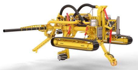
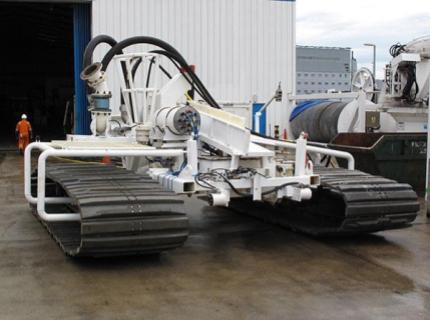 Figure 1
All the functions on the ROV are controlled hydraulically. The hydraulic control valves on the ROV are electrically operated. The ROV operates typically up to 300 m underwater on any given day which means the standard hydraulic solenoids (Fig. 2) on the valves will not survive.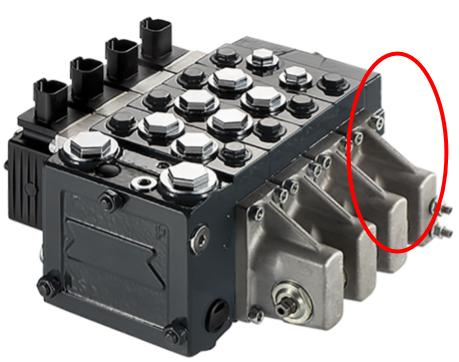 Figure 2
The current way of protecting the Valve Bank is to put it in a thick-walled stainless-steel box (Fig. 3). The problem with this is that to access the Valve Bank for the initial set-up, for maintenance, and for fault finding, the user has to loosen many bolts (Fig. 4).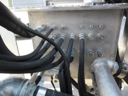 Figure 3
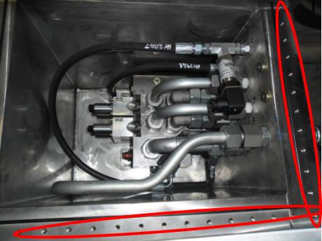 Figure 4
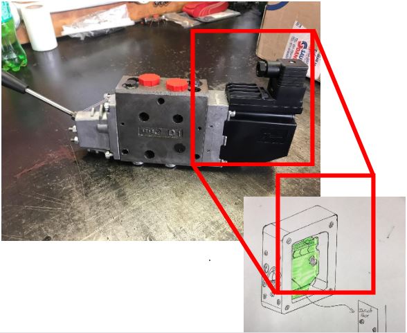 Figure 5
The OEM of the Valves does not provide detail information on the interface of the electronic control section and the valve body, so it was up to us to come up with novel ideas to copy the information (Fig. 6) and translate this to dimensions we could use on a CNC Milling Machine (Fig. 7)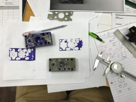 Figure 6
 Figure 7
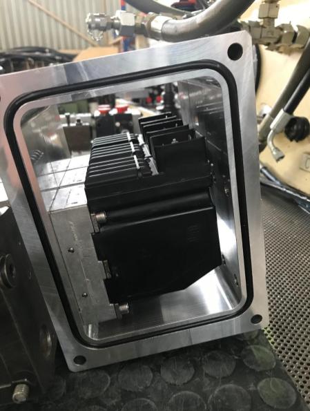 Figure 8
The electrical enclosures are matched to the number of valves required. Once sandwiched together, they are secured at the ends with End Caps with a Viewing Window, made of Polycarbonate, and 4 x High Tensile Tie Rods (Fig. 9).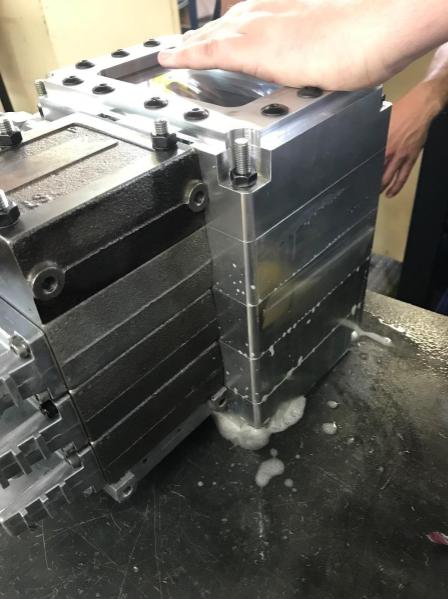 Figure 9
With the subsea pressure being so high it was decided to add a convoluted Bladder (Fig. 10) to compensate for the increase in external pressure.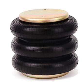 Figure 10
As shown in Fig. 11. The Bladder will compress as the ROV descends deeper into the ocean. This will increase the pressure inside the electrical enclosure to equal the pressure on the outside. This will reduce the stress on the enclosure as the differential pressure will be negligible as P1 ≈ P2 & P3 ≈ P4.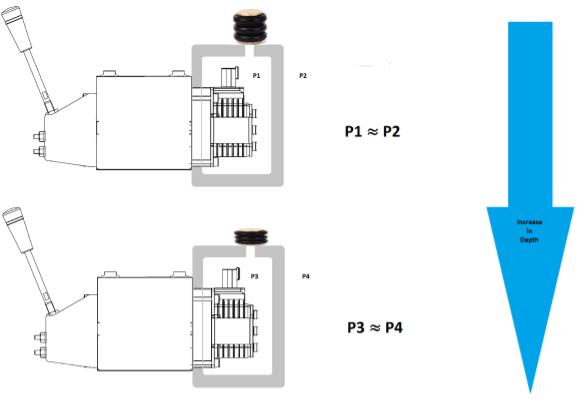 Figure 11
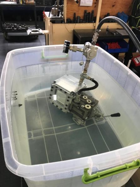 Figure 12
In a perfect world, the enclosure would have performed 100 % after the calculations were verified, the components CNC machined and finally assembled in a clean workshop. However, this is real life, and we identified a leak coming from the side of the window (Fig. 13). It turns out that the machinist made an error in positioning a bolt hole. This hole was TIG welded up and caused a leak at 5 Bar Air pressure, not even enough for the designed application. A new aluminum billet was ordered and a new End Cap was machined.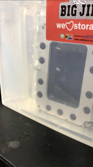 Figure 13
During the retesting, the electrical enclosure passed the 1st low-pressure test. In the 2nd round of tests, we planned to submerge the entire assembly in water: Similarly to the 1st round, but this time we would increase the pressure in the water and operate the hydraulic valve as per normal operation (Fig. 14). A thick-walled pipe was earmarked to form the body of the pressure vessel which would be pressurized to 31 Bar, equivalent to the pressure at 300 m below the sea surface. The pressure would be provided by a hydraulic cylinder pushing water into the thick-walled pipe (Fig. 14).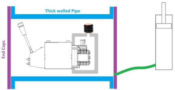 Figure 14
Unfortunately, at this point in the project, the Sales People came back and said the client had decided to stick to the existing solution for their current project. So the project was stopped and resources were reassigned. Figure 15
 Figure 16
Let us know other ways to successfully design a prototype for a Sales pitch and explore what ennomotive has to offer. Join our community of engineers
Success/Failure of a Prototype
In mechanical engineering, you often get assigned this kind of project: The Sales Department wants you to design a better solution for a Hydraulic Valve Bank Enclosure which will be used 300 m under the sea. Being an engineer, you revel in the chance to apply your skill set and experience to come up with a novel solution to the stated problem. But why would we, as a company, do this? Let’s start at the beginning. In an emerging market which is contracting, getting new business is crucial to staying alive. One of our clients in South Africa uses Subsea Remotely Operated Vehicle (ROV) similar to the ones shown in Fig. 1 to dig trenches to lay underwater communication cables.
Figure 1All the functions on the ROV are controlled hydraulically. The hydraulic control valves on the ROV are electrically operated. The ROV operates typically up to 300 m underwater on any given day which means the standard hydraulic solenoids (Fig. 2) on the valves will not survive.
Figure 2The current way of protecting the Valve Bank is to put it in a thick-walled stainless-steel box (Fig. 3). The problem with this is that to access the Valve Bank for the initial set-up, for maintenance, and for fault finding, the user has to loosen many bolts (Fig. 4).
Figure 3 Figure 4A solution to the problem
With the aim of winning the client over we set out to come up with a better solution. Because hydraulic systems are designed to keep high-pressure oil inside, the casings of the valve are typically robust enough to withstand the external pressures in our subsea application. So, we decided to just encapsulate the electronic control section as shown in Fig. 5. Figure 5The OEM of the Valves does not provide detail information on the interface of the electronic control section and the valve body, so it was up to us to come up with novel ideas to copy the information (Fig. 6) and translate this to dimensions we could use on a CNC Milling Machine (Fig. 7)
Figure 6 Figure 7Prototype Design
The electrical enclosure was designed in segments (one per valve slice, Fig. 8). 6083 Aluminium was chosen as the enclosure material due to its light weight, corrosion resistance, price, and availability. Each slice would seal up against the next one with an O-Ring providing the sealing. Figure 8The electrical enclosures are matched to the number of valves required. Once sandwiched together, they are secured at the ends with End Caps with a Viewing Window, made of Polycarbonate, and 4 x High Tensile Tie Rods (Fig. 9).
Figure 9With the subsea pressure being so high it was decided to add a convoluted Bladder (Fig. 10) to compensate for the increase in external pressure.
Figure 10As shown in Fig. 11. The Bladder will compress as the ROV descends deeper into the ocean. This will increase the pressure inside the electrical enclosure to equal the pressure on the outside. This will reduce the stress on the enclosure as the differential pressure will be negligible as P1 ≈ P2 & P3 ≈ P4.
Figure 11Testing
The 1st round of testing involved pressurizing the electrical enclosure chamber with Air at 5 Bar pressure and submerging the assembly in water (Fig. 12). Figure 12In a perfect world, the enclosure would have performed 100 % after the calculations were verified, the components CNC machined and finally assembled in a clean workshop. However, this is real life, and we identified a leak coming from the side of the window (Fig. 13). It turns out that the machinist made an error in positioning a bolt hole. This hole was TIG welded up and caused a leak at 5 Bar Air pressure, not even enough for the designed application. A new aluminum billet was ordered and a new End Cap was machined.
Figure 13During the retesting, the electrical enclosure passed the 1st low-pressure test. In the 2nd round of tests, we planned to submerge the entire assembly in water: Similarly to the 1st round, but this time we would increase the pressure in the water and operate the hydraulic valve as per normal operation (Fig. 14). A thick-walled pipe was earmarked to form the body of the pressure vessel which would be pressurized to 31 Bar, equivalent to the pressure at 300 m below the sea surface. The pressure would be provided by a hydraulic cylinder pushing water into the thick-walled pipe (Fig. 14).
Figure 14Unfortunately, at this point in the project, the Sales People came back and said the client had decided to stick to the existing solution for their current project. So the project was stopped and resources were reassigned.
Lessons Learnt
Many engineering design projects are cut short because the demand changes or disappears. This doesn’t mean the work done was not of good quality or that the engineering process was flawed. In a world were the demands change rapidly, it seems apt that the traditional engineering disciplines such as Mechanical Engineering can learn from software development and start using Agile Project Management techniques and apply principles such as:- Short repetitive Design Cycles
- Voice of Customer Input in Reviews after each Design Cycle
- Minimal Viable Product.
Figure 15 Figure 16Let us know other ways to successfully design a prototype for a Sales pitch and explore what ennomotive has to offer. Join our community of engineers