SHARE
Brushless Motor Controller for Curing Human Lungs
Designing a driver circuit for the driving and controlling a 3-phase brushless motor with hall sensors.
Case: The client requested the designing a 12v 10A speed controller to be used for a special type of a 3-phase brushless DC blower motor with about 35,000 rpm. The ESC (Electronic Speed Controller) had to be able to stop the motor instantaneously (The client had initially used a very expensive controller which was able to run the motor to its maximum RPM; however, it had a very poor control tuning that resulted in the jagged motor running.)
Since the work had medical application for curing of injured human lungs, the brushless motor controller had to meet the following requirements: It had to be designed in compliance with the given medical standards. Since the motor had hall sensors to allow it to start smoothly, the controller needed to be capable of providing such an input.
The speed had to be highly controllable with an accurate linear pattern and linearly increase or the motor speed to 35,000 rpm.
The final PCB design had to be as small as possible The final design had to be cost-effective Solution: Since there was no market available controller compliant with the conditions set by the client, the main challenge was to make a new controller from scratch.
So the following steps were taken: initially, an Arduino PWM system was considered to control the motor rpm but since the frequency produced by Arduino was much lower than the motor RPM, there was little control over the RPM.
In order to solve this issue, some books written for high-frequency applications were used. Software simulation of the design was made at each step to check every step. This method speeded up the design process.
The other challenge was the implementation of a security system to stop the power supply to the motor in such conditions as sudden stopping the motor. Initially, a current sensor was considered to be used for the system; however, since this would prevent a proper start for the motor, a short firmware was made to disconnect the sensor at the first 20ms after the start of the motor.
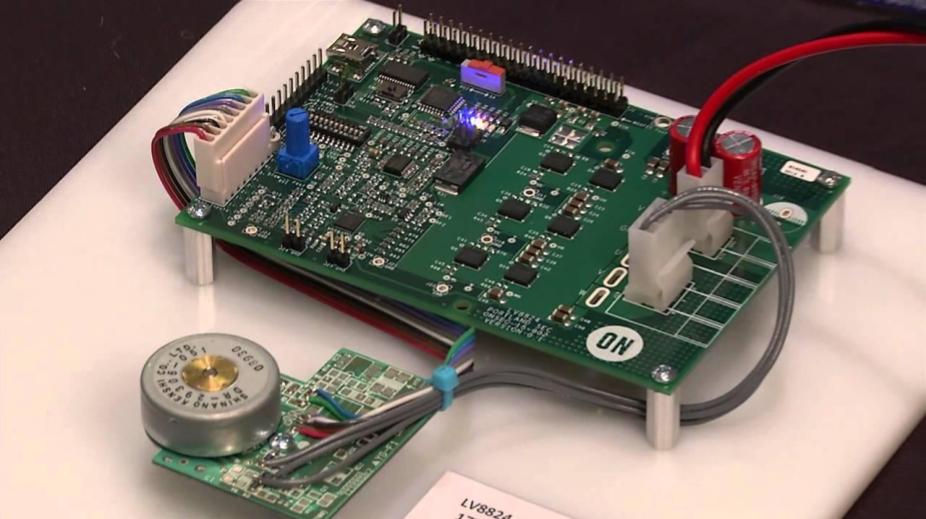
The final solution: The new driver was made by an Arduino Nano, six Darlington NPN and PNP transistors, and some logic gates. In the design, the analog signal was read by Arduino and then using a PWM system, the appropriate output was given to the transistors of the 3-phase bridge. Hall sensors where directly sensed by Arduino to determine the duty cycle of each phase.
After the design was made, it was checked with all the requirements set by the clients to make sure about its full compatibility with the given medical and design standards as well as cost requirements.
The final design cost was no more than £10.00 while the ESC used by the client cost £300.00 Results and Impacts: During the design, all the steps including the understanding stage, the initial block diagram, electronic design and finally making the prototype and the required tests were all shared with the client and were passed to the next stage with the complete approval of the client.
As a result, at the final step, the design received the full satisfaction of the client and so was a successful project.